Air Conditioning CAD Blocks: Split AC and Cassette
Three air conditioning CAD blocks in plan and elevation: a 900 mm wall split indoor unit, an 850 x 330 mm outdoor condensing unit and a 950 x 950 mm 4-way ceiling cassette.
Split AC indoor unit CAD block
AC outdoor unit CAD block
4-way cassette AC CAD block
- Units
- Millimetres (INSUNITS 4), scale 1:1
- Formats
- DWG 2010 · DXF R2010
- Opens in
- AutoCAD and AutoCAD LT 2010 or later, BricsCAD, ZWCAD and DraftSight. The DXF opens in most CAD programs.
- Views
- Plan view + Front elevation
- License
- Free for personal and commercial projects. License
Split AC CAD block plan and elevation
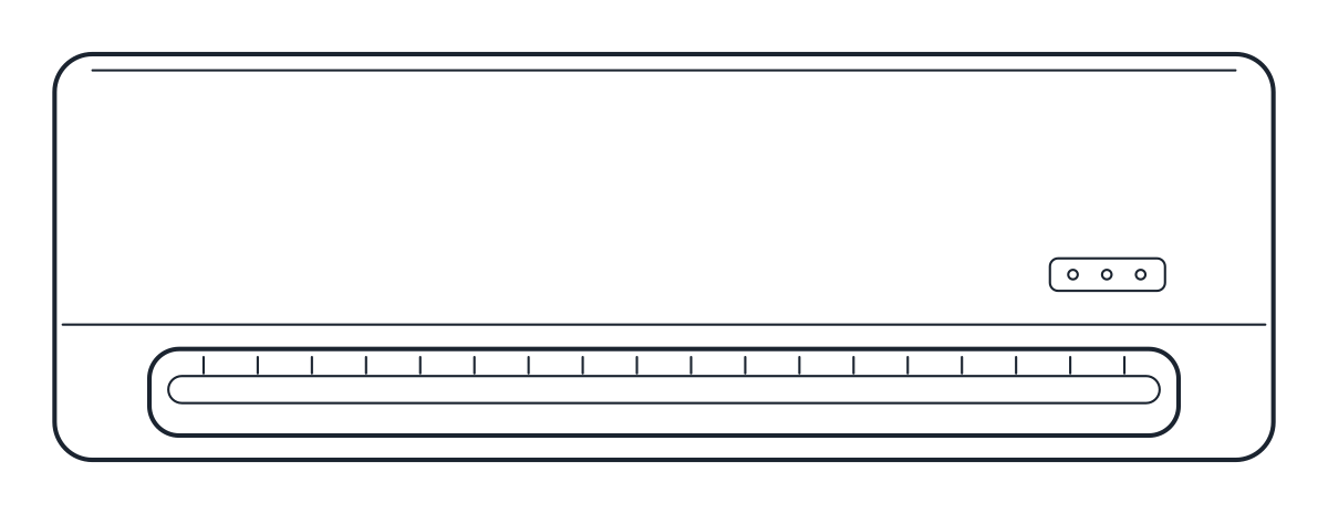
Each file holds two named blocks at 1:1 in millimetres, a plan such as CT_AC_SPLIT_INDOOR_PLAN and an elevation, CT_AC_SPLIT_INDOOR_ELEV. The wall-mounted split indoor unit is 900 mm wide, 230 mm deep and 300 mm high. It hangs on a wall plate with its back against the wall, so the plan block is a 900 x 230 mm strip that you snap to the inside face of the wall.
Air enters through the top grille and leaves at the bottom through a motorised deflector. In the room elevation, leave space between the top of the unit and the ceiling for the intake, using the figure in the manufacturer's data. The refrigerant pipes and the condensate drain run from the unit to the outdoor side, so place it on or near an outside wall when you can.
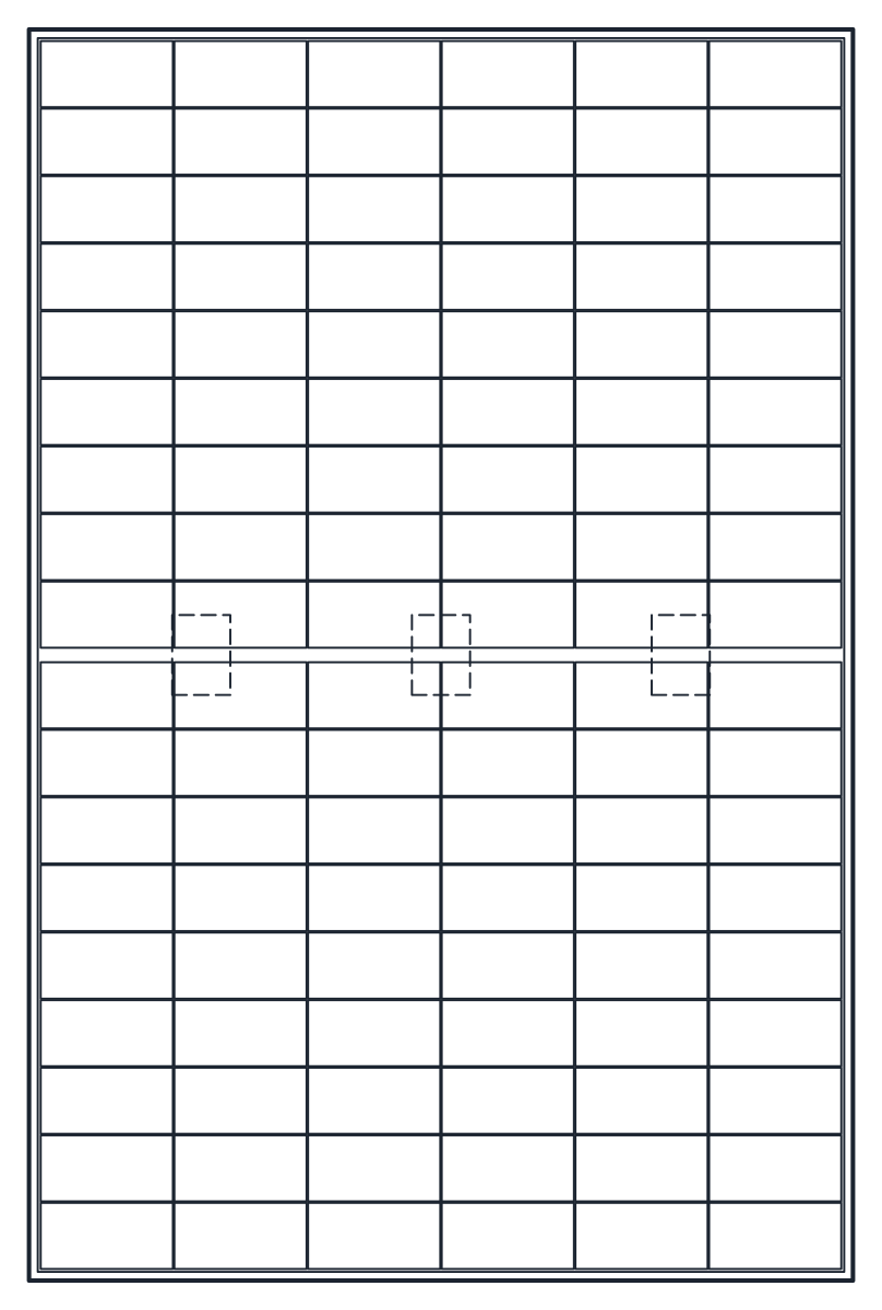
4 way cassette AC CAD block for ceiling plans
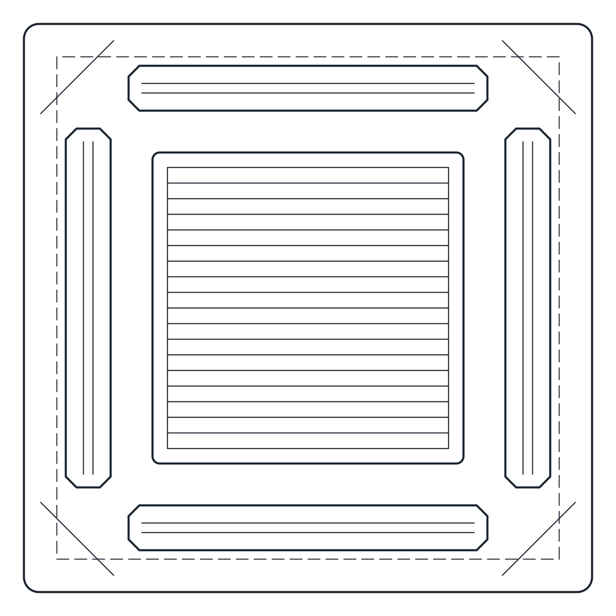
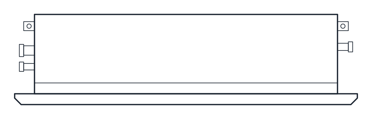
The ceiling cassette block is drawn as seen from below, for the reflected ceiling plan. The decorative grille is 950 x 950 mm and 30 mm thick, with a central return grille and filter and four discharge slots with louvres. The 840 x 840 x 220 mm body sits above the false ceiling, so it is dashed in plan and shown in the elevation. The whole unit is 250 mm high.
Compare the 220 mm body with the ceiling void before you choose a cassette, and add the hanging and drain allowances the manufacturer asks for. A 4-way unit throws air out on all four sides, so it works best near the middle of the area it serves.
AC outdoor unit CAD block and clearances
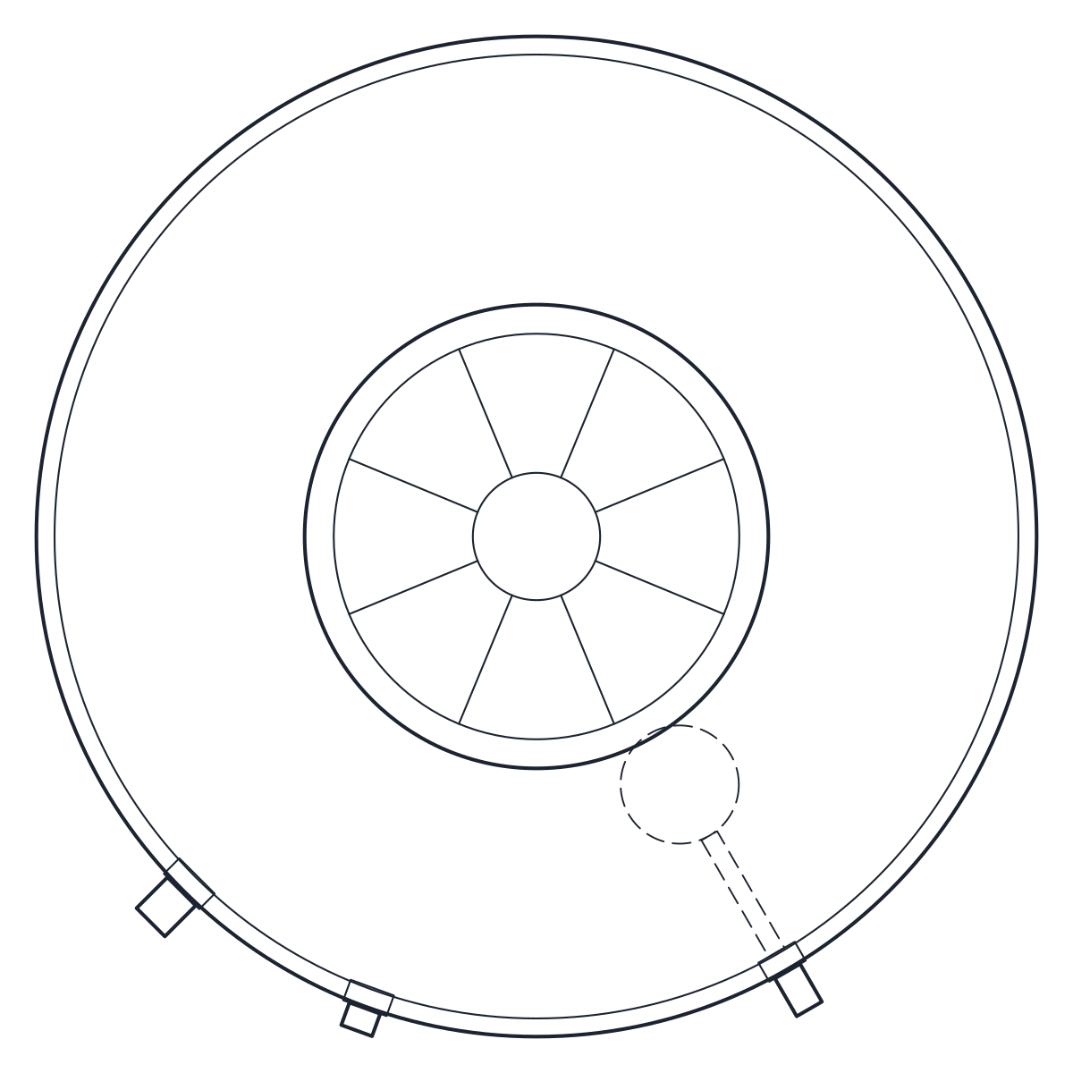
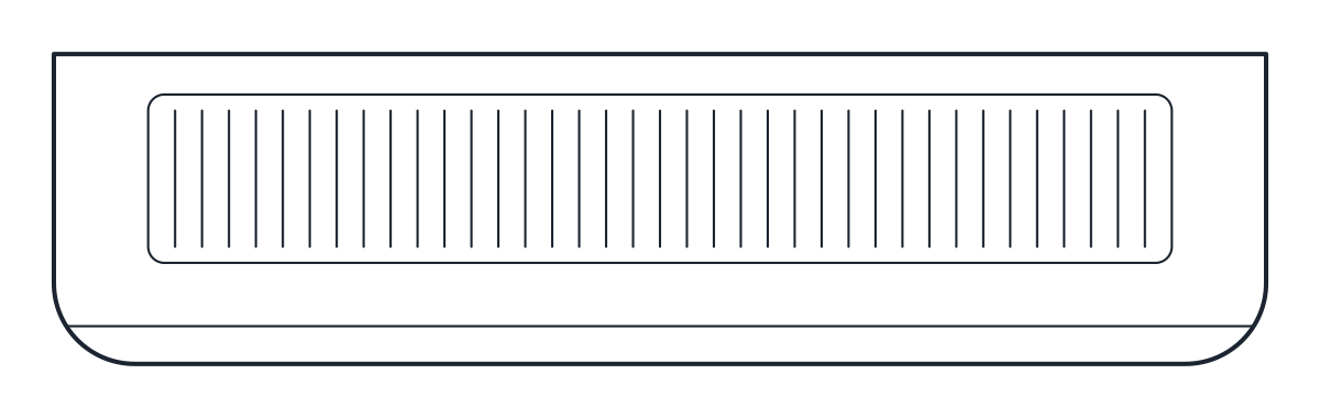
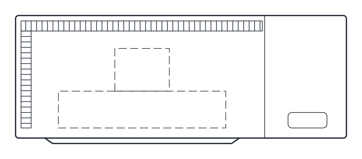
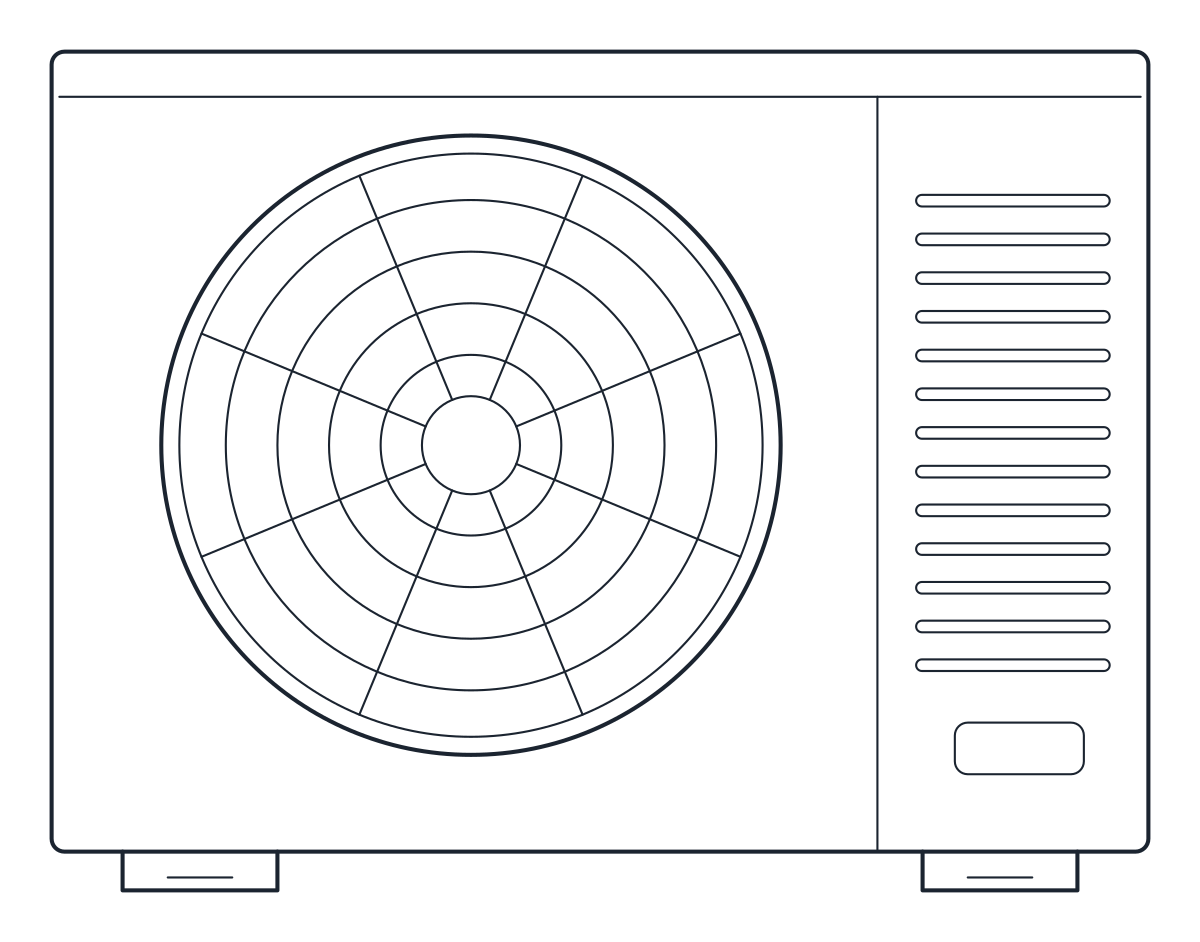
The air-cooled condensing unit measures 850 x 330 x 650 mm. It has one fan with front discharge and an L-shaped condenser coil on the back and the left side. The service valves and the electrical connections sit behind the right-hand panel. It can stand on feet or hang on wall brackets.
Keep the back and the fan discharge clear so the unit does not draw in its own warm air, and leave reach to the right-hand panel for service. The blocks carry no cooling capacity. Units grow with capacity, so replace the outlines with the dimensions of the model you select.
Air conditioner CAD block layers
Outlines are on M-HVAC-EQPM and grilles, louvres and fan details on M-HVAC-EQPM-DETL, with hidden parts dashed on A-HIDN. Freeze the detail layer for a clean equipment plan. Water tanks and solar equipment for the same drawings are in the HVAC, water tank and solar CAD blocks collection, and the guide to inserting a CAD block explains how to bring in only the plan or the elevation.